Software - Bike Walker
Image a bicycle, but replacing the two wheels with 4 legs. You sit on it, and peddle it, and the legs are articulated by a contraption of levers and gears. I don’t remember when this idea popped into my head, but I know that the huge tarantula monster vehicle in the Will Smith movie, “Wild, Wild West” certainly fueled the flames. I hadn’t given the idea enough thought to actually envision the nature of the mechanism, but just the general fuzzy image. Then one day, I saw a BMW commercial (on YouTube) that I’m sure was made for TV, about Defining Innovation. It shows a walking contraption that some dude from Europe invented. It was amusing, but more importantly, it was inspiring. I set out to see if I could design a similar contraption, then quickly realized I needed to start a new project!
So the premise of this application was to allow me to draw a mechanical structure including joints. Now, I know there are tons of CAD systems out there that can do this quite nicely, but my object was not to “find” something, but to “write” something – after all these projects are for fun, right? So I WROTE a simple CAD user interface to allow me to draw legs and joints of my concept mechanism, and manipulate it easily to assist me in design and analyze the motion. I don’t claim any ground-breaking functionality here, but I did write the software specifically to aid in designing the walking-leg mechanism. My first design (admittedly) looked like one of the legs on the contraption I saw on the YouTube video, but my analysis concluded that it simply didn’t provide a motion I was happy with, so wrote more code to help me explore variations by moving joints around and adding more complexity to the system. During the design phase, I went through a LOT of variations, and the one we (the software and I) concluded with was highly optimized for both simplicity and motion criteria.
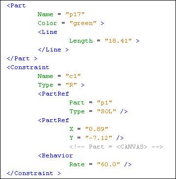
Like all of my other software project (so far) this application uses an XML database, and (departing from previous versions) a custom XML I/O suite. And, unlike the previous software projects, whose objective was to build an infrastructure that would render a robotic mechanism, this object of the infrastructure of this project was to facilitate maturing the design of the data model itself.
The software itself was only a design tool, to conclude with the dimensions of a mechanism. Somewhere along this software project I began an ambition towards actually building this contraption. That’s when I started planning the Hardware category of my Projects (not to mention my whole work-shop).
Details
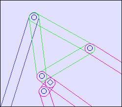
The Bike Walker design & analysis program is a Graphic User Interface, like a (simplified) CAD system, and was written to allow me to add, modify, and analyze the 2D structural components that will be used in the Bike Walker hardware project.
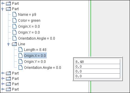
Lines can be created by clicking a point and stretching (or “rubber banding”) to another point. Points can be fixed in space or be joined (or “constrained”) onto other Lines. Lines are drawn with a desired width and color for esthetics, and clarification. Data details can be edited either in a graphic form or in table form.
Existing points can be dragged around, either moving one end of a line or modifying the two lines it joins, as the case may be.
One line fixed in space can be continuously rotated or manually incremented clockwise or counterclockwise as desired. The lines are automatically networked to honor the movement of the rotated line and constraints of the lines and joints to animate the entire structure correctly.
The lines and hinges can be labeled to identify them.

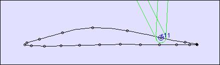
The movement can be visualized by selectively plotting lines as fans that they sweep through, and joints as curves that they move through. The dots are constant-time marks throughout the cycle.
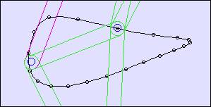
An analyzer simultaneously modifies all of the line lengths to maximize a weighting criteria that produces an optimal desired movement. The criteria is that the bottom-most hinge (the foot) would sweep through a motion that would simulate a walking foot – move along a straight level line at a constant speed for greater than half the cycle, then rise and quickly return to the beginning of the straight level line again.
The line and joint parameters can be loaded and saved to the data file (XML) for re-use.
The line length, and joint placement geometry was transferred to a 3D solid model in a robust CAD system for further modeling and design details – see the Bike Walker Hardware Project.