Mill - Mods & Upgrades – Digital Read-Out (DRO)
Measuring parts during fabrication with a micrometer or caliper, or by counting turns and tick-marks on a wheel is for the birds! Another of the early decisions I made was that I needed a more precise method of producing better precision than I currently had at my disposal. I’ve always wanted to go into CNC, but was convinced that that’s a pretty big leap, and I need to make a lot of smaller steps toward that beforehand. A mediocre machine with a good DRO can put out some pretty good parts, for a WHOLE LOT less than a really good machine. And in the industrial world, almost ALL non-CNC machines at least have a DRO on them. So I thought that is what I ought to do next.
My research led me to a simple solution from Shars.com: a 3-axis DRO. It consists of measurement rails, with a measurement head, and a controller box. The rails mount on the 3 axiis, and the box mounts about eye-level along the side of the head.
I read a brief description somewhere about installing it, and figured it was doable. So I bought it and went to work on installing it. I think I’ve determined that these things were designed for installation on MUCH larger machines than mine, because the rails looks kind of gangly there on my little bitty mill, but I got it all to fit.
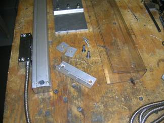
ALL the mounting hardware that was provided with the unit was useless. I bought a bunch of quarter-inch thick aluminum plate, and made all the mounting hardware from scratch. I have to admit I think it turned out really, REALLY nice. I also decided to shield it all with Lexan sheet to keep chips and coolant away from the tender parts. I not only had to make all the mounting parts, I also had to form the Lexan around the measurement rails.
I started by modeling the dimensions of the critical areas of the mill in a CAD system, so I could design the parts a little better than just by-gosh-and-by-golly. I still had to make all the parts with low-precision tools, but with a little trial-and-error, I was able to make some pretty good mounting hardware. I read how to form Lexan by heating it GENTLY over a mold, so (again) after a little trial-and-error, I made some very nice shields that fit (mostly) pretty good around the rails.
I got 1/8–inch Lexan sheet from Home Depot ($35 or so) and cut it with on the band saw and a hand-held jig-saw. I used a couple pieces of 3/4-inch aluminum L-shape as my mold, and a little butane torch to SLOWLY warm it up so it laid gently over the mold, then put another angle over the top of it and whack it with a rubber mallet. Voila!!
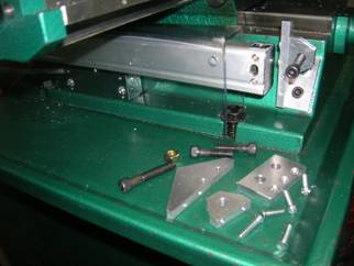
Here is one of the Y axis rail mounts assembled and installed, and the other end disassembled on display. I drilled and tapped mounting holes in the base.
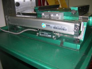
Here is the Y axis rail assembled and mounted (with the table removed). Notice the Lexan cover. The slider-sensor is bolted to an L-shape, bolted to a plate, bolted to the cross plate. The L-Shape and plate provide a space for it to move back and forth under the cover. Note that the base mounting bolts (front and rear) were relocated to new drilled and tapped holes to allow the slider-sensor to traverse the full range of the Y-axis.
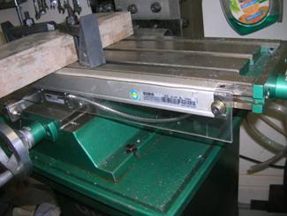
Installing the X-axis rail was rather uneventful. I fabricated a small plate and mounted it to the front of the cross plate, and directly to the slider-sensor. The cover is just a rectangular plate of Lexan, and hot-glued a few places along the length of the rail. The rails were bolted to the wedge nuts of the end-travel bolts of the table. I felt bad about giving up the space where the X-axis lock-bolt was to the rail; I’m still thinking about somewhere else I can replace it to instead.
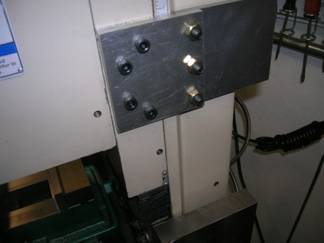
The Z-Axis was a lot more elegant. I fabricated a plate that attaches the slide-sensor to the vertical slide. And a couple of mounting off-sets to allow space for the Lexan cover behind the rail.
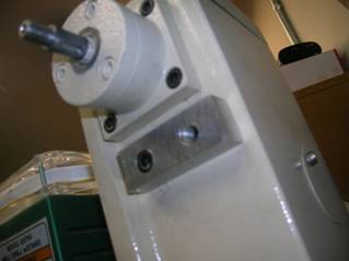
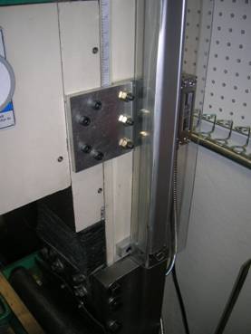
The rail mounting plate serves two purposes: because the vertical column sides are rounded I needed a stable surface to bolt the rail to, and like the Y-axis rail, I had to lift it out a bit to provide space for the Lexan shield to fit around it and for the slider-sensor mounting plate behind it.
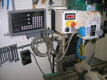
The result is that I now have (a confirmed) two-tenths precision – that’s .0002. That’s pretty good for this kind of machine. I’ve exercised the heck out of it, and it seems to be right on the mark every time.
Whereas before, all I could do was low-precision rough-cuts, now I can do hi-precision finish-cuts, holes, etc. Now all I need are some better hi-precision skills! Ha! You start with good tools, add good instruction and skilled mentorship, and a LOT of practice, and skills will come. I think the DRO was the best investment upgrade I’ve made to the mill because it gives me the tools to actually do much better work than before.